Front View
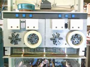
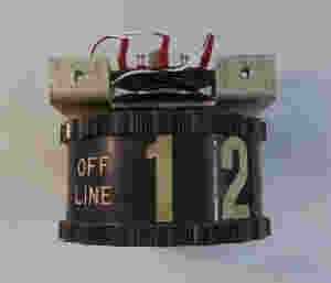
You can see the backplane carrying the boards and cables. Notice there are no drive-select dials or switches. As configured, the left drive is 1 and the right drive is zero. I managed to obtain a couple of older TU-55-style drive number switches (see picture below) and will add those to a panel above this unit once everything else is operating properly.
Peeking over the top of the drive is the bottom part of a paper tape reader planned for interfacing later. Not part of this project.
Rear View
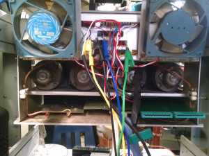
The rear view doesn't show much. You can see my 'Mission Impossible" wiring clips in place supplying the +5 and -15v power supplies. The fans have been tilted up to make easier access to the card slots.
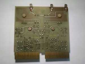
Component side of Motor Drive card
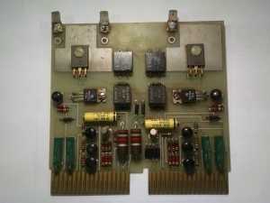
The motor drive board appears to be mostly a dual version of the G850, though I have not finished tracing this board yet. It has the same pulse transformer (Sprague 1:1 PT-55 as listed in the DEC schematic.)
Circuit side of Motor Drive card
Component side of Motor Logic car
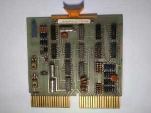
The Motor Logic embodies the logic for all of the DECtape motion commands as well as control switch functions. I've created a KiCAD schematic of this board in order to reverse engineer the external control connections. The schematic is here.
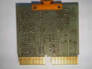
Circuit side of Motor Logic card
Closeup of handle of Motor Drive card
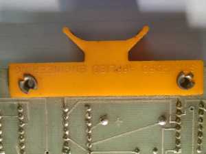
A close-up of the handle on the C849 board showing the Stanford Applied Engineering stamp.
Component side of Head Switching relay card
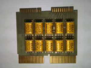
ICS also created a 'dual' version of the Head Relay switching board. This board appears to be a duplicate of a G851 relay board, but added a second rank of relays controlled by pin 2V2. Also notice the connector for the DECtape head cable: instead of the wide single-row edge pins, it contains two 22 pin (11 pins per side) set of fingers. The strange thing is the mating cable contains a 2x12 connector (24 pins!) so when connecting the cable to this board, one needs to be aware that one of the connector's pins will be 'floating' at the end of the connector, so alignment is manual and critical.
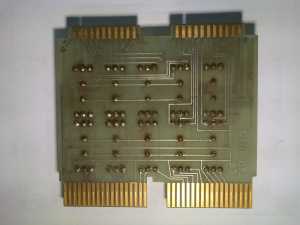
Circuit side of Head Switching relay card
Component side of head Cable card
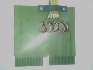
Pretty standard layout here. I think this matches the DEC standard 5-head connector cable.
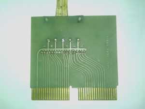
Circuit side of Head Cable card
Drive Select switch
